Moin Ludger,
auch wenn dein Post schon ein paar Tage alt ist, vielleicht ist folgender Tipp von mir als langjähriger JR PCM 10sx / PCM 10 x User für dich hilfreich:
Das von dir geschilderte Phänomen tritt auf wenn Senderakku UND gleichzeitig die interne Stützbatterie leer waren (Abschnitt What to do if faced with a ‘DEAD’ radio). Dann hilft nur der Tausch der internene Stützbatterie, ein nachfolgender Factory-Reset und anschliessend eine neue Kalibrierung der Sticks. Früher hat man in so eionem Fall die Funke zum Service eingeschickt. Ich habe aber im Netz diverse JR-Seviceunterlagen gefunden, die mit etwas technischer Kreativität auch auf die X22 angewendet werden können. Die beschriebenen Prozeduren gelten wahrscheinlich auch für andere Modell die als in den Unterlagen Aufgeführten.
PS: Falls du elekrisch nicht so bewandewrt bist und dir das Ganze "too much" erscheintt und bevor du den Sender in die Tonne trittst, sag mir bitte Bescheid - ich nehme ihn gerne.
Guude aus Südhessen
Walter
Replacement of the Lithium Cell in a JR radio
JR must have recognised the problem of replacing the lithium cell without losing all the customer's settings. When the set is taken apart the main battery is first removed, then the circuit boards come out to gain access to the cell. When the cell is removed there is no current to retain memory - or is there? This is the part they don't tell you about. There are capacitors in there which retain enough power to sustain memory for several hours, plenty long enough to fit the new cell - BUT - you must switch the set on for a brief period before you start so as to charge the capacitors. If you don't do that you will almost certainly lose your settings.
JR claims a 5-year life for the lithium cell in its computer radios. In practice, it will usually last much longer - 10 years or more. It is very much dependent on how often you use the transmitter. When you turn on your Tx, the main battery pack supplies the voltage to the PCB. Part of this goes to a voltage regulator that supplies 5v and charges up the capacitors. When you turn off the Tx, the capacitors supply the memory section of the CPU. The charge on the caps will take some hours to discharge, but when it hits about 3v the lithium battery then takes over. The lithium drain current is in the order of 2 - 5 microamps. The CR2032 cell is rated at 240mah, so at 2 microamps it should last about 13 years, while at 5 microamps it will be around 5 years.
So if you fly daily, then the lithium will hardly ever need to supply the "keep memory" voltage, and the lithium will last in excess of the nominal 5 years. If you fly weekly, then the lithium supplies the voltage more often. If you fly rarely then the lithium is supplying this voltage most of the time and will deplete itself closer to the 5 year point.
Note: The CR2032 cell can be supplied with or without solder lugs. You need to specify “CR2032–1HF W/Legs”.
Instructions:
1. As a precaution, copy all your model settings on to the appropriate data sheets.
2. Switch radio on briefly, then off, to charge the capacitors.
3. Remove the module from the back of the radio by squeezing the lugs and pulling it out.
4. Remove the battery cover and remove the battery.
5. Remove 4 screws from the rear four corners and the 2 screws from the antenna base.
6. Carefully separate the 2 halves of the transmitter, starting at the base.
7. Unplug the multi-pin connectors to separate the halves completely for ease of access.
8. Remove the circuit boards to gain access to the CR2032 cell.
9. Unsolder the cell and remove it. Solder in the new one.
10. Reassemble, not forgetting the multi-pin connectors.
What to do if faced with a ‘DEAD’ radio.
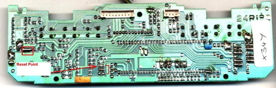
If after fitting the new cell, or for some other reason, there is no response from a JR Tx when switched on, it may be possible to revive it with a ‘factory reset’.. On the main circuit board, somewhere near to the CPU, there will be a pair of contacts which, when shorted (with say a pair of tweezers) will initiate a reset. Switch off, then on, and the radio should come to life! The contacts will be unvarnished and have the word ‘RESET’ or ‘RES’ or just ‘R’ beside them. See attached illustrations of circuit boards for the 347/388/783 and 642/652. The JR 7202/2720 series apparently do not have a reset point.
After a successful reset, the stick units may possibly require recalibration – refer to the appropriate Service Menu document for the procedure.
Factory Reset Procedure - 347 / 388 / 783
1. Leave battery connected.
2. Remove 4 screws from the rear four corners of the Tx, and the 2 screws from the antenna base.
3. Carefully separate the two halves of the transmitter, starting at the base.
4. The main circuit board is positioned along the bottom of the case. The 64-pin micro-processor is mounted on the other side of this board, but you can identify its position by the two rows of 32 soldered pins. Towards the left of the bottom row of 32 pins there is a letter ‘R’ beside a pair of soldered pins, one of which is connected via the PCB to pin 29 on the processor - check by counting back along the row from the left-most pin #32. The other pin is connected to ground.
5. The objective is to short pin 29 to ground with the transmitter turned on - refer to attached photo. Use a pair of tweezers. The radio will then enter Service Mode (INTL displayed) then by pressing CLR all the factory defaults will be restored.
6. Switch off and re-assemble the transmitter.
Factory Reset Procedure – 6102
(from MacMan)
To the right of the CPU on the PCB you will see the CPU Xtal (upper right side) to the immediate right there are 2 solder pads marked "Res". With power on, short these 2 pads temporarily, the set should Beep at you. Turn off and back on and hopefully it will now display correctly.
6. Switch off and re-assemble the transmitter.
JR Service Menu – X-347, X388S, XP783
Screen 1 INTL (Indicates you are in Service Menu)
If you press CLR when in this screen you will lose all your settings and the TX will be in factory default.
INTL CLR: indicates that you have lost all your settings and you are in factory default!
Use the UP key (or DN for reverse sequence) to scroll through the following functions:-
Screen 2 Stick Calibration
(This procedure is like calibrating a joystick on a Windows PC)
With the sticks and pots centered, check that the pot values are close to 0.
Use the CH key to scroll through STK.1 to POT.8 while looking at the displayed value.
A tolerance of ± 4 is acceptable. If necessary, mechanically adjust the stick pots so that a value close to 0 is achieved.
STK.1
STK.2
STK.3
STK.4
POT.6
POT.7
POT.8
Press the UP key to move on to -
Screen 3 Trim Lever Calibration
Similarly set all trims to a centre position. Use the CH key to scroll through the four trims, checking that a value close to 0 is displayed. Adjust mechanically if necessary.
TRM.1
TRM.2
TRM.3
TRM.4
Screen 4 Switch and LCD display test screen only: 00#0 0#00
Screen 5 Stick end point calibration:
SA1 (See notes below
SA2 (to determine
SA3 (which stick
SA4 (to move.
Move the stick to one end point and press the CLR key.
Move the stick to the other end point and press the CLR key.
Select a new stick with the CH key and repeat this for all four sticks.
When all 8 end points are stored the SA# will stop flashing:
Notes:
STK.1, TRM.1, SA1 = Elevator (mode 2) or Throttle (mode 1)
STK.2, TRM.2, SA2 = Aileron
STK.3, TRM.3, SA3 = Throttle (mode 2) or Elevator (mode 1)
STK.4, TRM.4, SA4 = Rudder
Screen 6 Transmitter voltmeter adjustments:
(Apparently the stick calibration can be affected if the displayed voltage does not match the actual battery voltage.)
Hook up a reliable digital voltmeter to the transmitter battery and adjust the transmitter voltage display with the DATA+ and DATA- keys to read the same or slightly below the digital voltmeter: ~ 9.6V
Screen 7 Enable or disable optional features:
These items can be ACTivated or INHibited. Press Data + or Data – to toggle the setting:
The setting in bold type is the normal or factory setting
BATT NICD or DRY
Press CH or CHANNEL to scroll through the following options:
ALRM 9.3v or 9.0v Sets low battery alarm to sound at 9.0v or 9.3v as desired. (Useful if the Tx battery is getting old and you want a greater margin of safety.)
SDIR ACT or INH Reverses throttle stick – Low throttle is UP.
SWMX ACT or INH Activates Cyclic Collective Pitch Mixing. (The user can then make Swash Selection in a heli model setup, i.e. Normal, 2 servos, 3 servos, or 4 servos)
SMOD ACT or INH Activates Stick Mode change option. (Stick Modes 1, 2, 3 or 4 can then be selected from within the System Menu)
MAX CH n n = max no. of channels, 7 or 8.
(Note: a 7-channel 783 can be changed here to an 8-channel set)
TRNS ACT or INH Undocumented facility for transferring model setup data (one model at a time) from one X-347, X-388S or XP783 to another X347,
X-388S or XP783. If activated, a new item as follows will appear in the System menu:
TXDn *STR (where n= aircraft model no.)
(See Appendix I below for detailed transfer procedure)
POT8 YES (388) or NO (347)
Screen 8 TxD * STR : Data dump function. This facility allows the user to transfer ALL data from one Tx to another. Could be used to save all data of a client before work is done on their radio. All model setups and mixes are transferred in one operation. The procedure is shown in Appendix II. [May possibly be used with a program such as JR’s Datasafe to store the data on a PC, but this has not been tested yet.]
Screen 9 369.8 00:00 : The first four numbers represent the non-volatile memory address in hex and the next four is its value. Use + or - to page through. Allows a technician to examine the contents of memory addresses.
Appendix I
Procedure for transferring model setup data, mixes and settings from one Tx to another, ONE model at a time.
A JR trainer cord is required.
Ensure that the Service Mode menu item TRNS has been ACTivated.
1. Take the Tx which contains the model setup data to be transferred (the sending transmitter). Leave switched off. Hold Up/Dn keys while inserting trainer cord. The set will beep; you are in System Mode.
2. Use the + or – key to select which model you want to transfer. Press DN twice to display TxDn *STR where n is the model number.
3. Take the Tx to which the model setup data is to be transferred (the receiving transmitter). Leave switched off. Hold Up/Dn keys while inserting the other end of the trainer cord. The set will beep; you are in System Mode.
4. Use the + or – key to select which model number is to receive the data. Press DN twice to get TxDn *STR where n is the model number. Switch on, it will then show RX Dn STR. Press CLR and it goes into stand-by: RXDn STBY.
5. Return to the Sending Tx and press CLR to transfer the data.
6. The Receiving Tx now displays RX Dn OK. Data has been transferred.
7. If further model setup data is to be transferred, switch off, remove trainer cord, repeat 1 – 7.
Appendix II
Procedure for transferring model setup data, mixes and settings for ALL models from one Tx to another. This operation is carried out in Service Mode.
A JR trainer cord is required.
1. Place the Sending Tx in Service Mode.
2. Press DN twice to display TXD *STR
3. Insert the trainer cord. The display changes to RXD STR.
4. Press CLR and it goes into stand-by: RXD STBY.
5. Switch off. RXD STBY remains displayed.
6. Press UP then DN.
7. Display is back to TXD *STR
8. Place the Receiving Tx in Service Mode.
9. Press DN twice to display TXD *STR
10. Press CLR and it goes into stand-by: RXD STBY.
11. Return to the Sending Tx and press CLR. All data will be transferred.
12. On completion the Receiving Tx will display RXD OK.
Appendix III
The following procedure puts a new menu item in the Function menu. The display reads OUT.1 xxx where xxx is the signal output value for each channel. Pressing CH brings up OUT.2 through to OUT.8. It's not quite the same as stick calibration, because the displayed value includes slider trim settings plus any subtrim settings. It is obviously the final value sent to the servos and is probably used for trouble-shooting. The menu item is
only temporary and it disappears once the radio is switched off. It could be useful if you need to check those values any time you are dealing with a problem Tx.
Procedure -
Enter Service Mode
Exit Service Mode by pressing UP DN together.
Enter Function Mode by pressing UP DN together.
Press DN twice.
OUT.1 0 (or other value) will be displayed. If sticks are centered and
trims are all at zero, including subtrims, the displayed value will be 0 or
close to it. By moving the appropriate stick or pot you will see a change in
the displayed value. Cycle through the 8 channels with the CH button.
The memory addresses, normally seen in the Service Menu, also appear
temporarily in the Function Menu.
Das Bild im Anhang zeigt exemplarisch die Rest-Kontaktpunkte die kurzzuschliessen sind für ein Board der Serien 347-388-783. Für die X22 müsste man diese analog auffinden können.